TitlePages

Wednesday 24 December 2014

ArcGIS Python Mapping Module


Arc Python to interact with Arc-map

What is ArcPy Mapping and Why is it actually used for :

Arcpy.mapping was built for the professional GIS analyst (as well as for developers). Traditionally, the scenarios listed above had to be done using ArcObjects and it often proved to be a very difficult programming environment to learn for the average GIS professional. Arcpy.mapping is a courser-grained object model, meaning that the functions are designed in a way that a single arcpy.mapping function can replace many lines of ArcObjects code. The following is a very simple example of how arcpy.mapping can be used to reference an existing map document and export it to a PDF document with only two lines of code.

To explore the Overall Arcpy mapping Module use the following PDF:

Arcpy Python Mapping Module


Code for Getting the reference to the MXD :

YourMXD= arcpy.mapping.MapDocument("path to the MXD")

To export the above MXD to PDF using arcpy:

arcpy.mapping.ExportToPdf(YourMXD,"your pdf file")


Get Reference to the Current Arcmap
Pointer to a MXD present on the Disk


Map Layout Document in the Arc map
Layout View of the Map Document

Arcpy.mapping is not a replacement for ArcObjects but rather an alternative for the different scenarios it supports. ArcObjects is still necessary for finer-grain development and application customization, whereas arcpy.mapping is intended for automating the contents of existing map documents and layer files.


Creating Geodatabases using Arcpy or Model builder

Creating Geo-databases in Arc Map

What is a Geodatabase:
  • A geodatabase is the common data storage and management framework for all the ArcGIS Products. It combines Geo (spatial data) with Database (data repository) to create a central data repository for all the spatial data storage and management in your ArcGIS platform.
  • It can be leveraged in desktop, server, or mobile environments and allows you to store GIS data in a central location for easy access and management.
The geodatabase offers you the ability to
  • Store a rich collection of spatial data in a centralized location.
  • Apply sophisticated rules and relationships to the data.
  • Define advanced geospatial relational models (e.g., topologies, networks).
  • Maintain integrity of spatial data with a consistent, accurate database.
  • Work within a multiuser access and editing environment.
  • Integrate spatial data with other IT databases.
  • Easily scale your storage solution.
  • Support custom features and behavior.
  • Leverage your spatial data to its full potential.
Arc-map geodatabase can be created using various way:
  1. Manually creating through Arc-Catalog
  2. Using the Model workflow to create it Programmatic-ally
  3. Using the Python integrated to Create Geodatabase Programmatic
  1. Model for Creating Feature Class
Model to create Geodatabase in ArcGIS
Set the workspace and OutputFC as the Model parameter

AddField will add a column to the newly created Feature class and can be populated with the user defined values

The Search, Insert or Update cursor can be used to manipulate the values present in the new Feature class

For achieving the above functionality it is advised to write a python code using the arcpy library.

To know more detailed step by step information about the creating a feature class in the Geodatabase
Click here - Create Geodatabase Feature Class - PDF


Arcpy Improvements in 10.1

Arc Python in ArcGIS 10.1

  1. Site package that adds ArcGIS functionality to Python
  2. Access to rich suite of geoprocessing tools
  3. Functions, classes and modules
  4. Helper functions like ListFeatureClasses, Describe
  5. Classes that can be used to create complex objects like Spatial Reference, Field Map
  6. Modules that provide specialized functionality like Mapping,SpatialAnalyst, NetworkAnalyst, DataAccess

Complete Introduction to Python concepts for beginners is available here

Python
ArcGIS + Python = ArcPython

For more info and advance Concepts use the folowing references: 

resources.ArcGIS.com
arcpy.wordpress.com
GIS Stack Exchange, Stack Overflow
Python References,Python Scripting for ArcGIS
GIS Tutorial for Python Scripting by Allen (Esri Press)
Learning Python by Lutz - The Python Standard Library
python.org
http://www.esri.com/training

Exporting the feature class to CSV Format


Exporting Geodatabase toComma Separated Value Format

Let start creating an python addin for converting the feature class in your geodatabase to CSV format.So that everyone can understand your feature class and its values.
  • If you are very new to python addin then go through- How to start with python addin 
  • The input feature class and output csv file path are hard coded in the sample program
  • For dynamic conversion get the path of the files through a variable and pass it as a parameter to the defined functions
Comma Seperated values
CSV Fromat


def ex_fc_to_csv(fc, out_csv):
    """
    Export all vertex in a line or poly feature class to a csv with OID
   
    example

        import geom_snippets
        geom_snippets.ex_fc_to_csv(r"c:\proj\fc1.shp", r"c:\proj\fc1.csv")

    output csv looks like this

        1,56019.99998067904,69118.00001450378
        1,56159.99998080942,69026.0000144181
        1,56359.999980995686,68913.00001431286
        2,34985.00002508866,68936.00001433428
        2,35178.000025268404,68805.00001421227

    """
    import csv
    import json

    with open(out_csv, 'w') as csvfile:
        csvwriter = csv.writer(csvfile, delimiter=',', lineterminator='\n')

        with arcpy.da.SearchCursor(fc,
                                   field_names=("OID@","SHAPE@JSON")) as cursor:
            for row in cursor:
                geom = json.loads(row[1])
                for path in geom['paths']:
                    for pt in path:
                        csvwriter.writerow([row[0]] + pt)

Monday 15 December 2014

Story Telling Maps - on ESRI News

James Douglas Skinner AirForce Navigator Story Maps


Story Telling Maps


GIS for real life Applications and Intergating with GIS Devices

GIS Future Technologies

Introduction

Global positioning system (GPS)  technology has complimented geographic information systems (GISs) for a number of years and is now well understood and accepted by the GIS community. The primary focus of GPS within the GIS arena has traditionally been based around GPS systems that collect, store and transfer data from a field system to an office-based GIS. With current developments in field computers (especially related to lightweight and low cost devices that operate Microsoft's Windows CE operating system) there is a strong desire to take GIS directly into the field. This increased interest in field-GIS has a corresponding interest in the application of GPS within GIS.

GIS/GPS Integration Techniques

There are three basic ways that GPS technology can interact with or be integrated into GIS. The level of integration associated with these vary from a 'disparate' connection, whereby data is transferred between a GPS system and a GIS system, through to a very 'tight' level of integration, whereby GPS technology is totally embedded directly within GIS application software. GIS/GPS integration can be categorized into the following three categories:
  • Data-focused integration
  • Position-focused integration
  • Technology-focused integration
The appropriateness of each method is dependent upon the requirements that a user has for field-based operations, the level of dependence the user has on GPS and, to a large extent, the availability of a complete system to meet the specific needs that the user has for a system.

Data-focused Integration

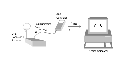
To date, the most common method of integrating GPS into GIS has been through a data-focused method of integration. (Although the term 'interaction' is probably a more appropriate term than 'integration'.) Data-focused integration, as depicted by Figure 1., utilizes a complete, self-contained GPS system that has data collection and storage capability for use in the field. Data that is collected in the field is later transferred to an office PC for processing and eventual export to an enterprise GIS that resides within an organization. Historically, data-focused systems have concentrated on a one-way data flow whereby data is transferred from the GPS product to the GIS database. GPS field products are now emerging, however, that allow data from the GIS to be uploaded as well, so existing data can be taken easily back to the field for data update and maintenance purposes.
Conceptual view of data-focused integration
Figure 1. Conceptual view of data-focused integration
Self-contained GPS systems used in this manner are complete in themselves and generally developed by large GPS manufacturing organizations. The system consists of a GPS receiver, GPS antenna and a controlling device with data storage capability. Units can be either modular (as stylized in Figure 1.), fully integrated into one housing or a combination of the two. Historically, GPS systems have been rugged, to cater for harsh outdoor environments, with self-contained software that is optimized for limited storage, keyboards and screen real estate. These GPS systems are usually designed to meet the needs of most data collection or data maintenance professionals and are purchased as an off-the-shelf, turnkey system.
The primary advantage of utilizing a data-focused approach to GIS/GPS integration is that an end-user can operate the GPS system "out of the box" with little or no need for customization. For many GPS users, an off-the-shelf system will cater for most, if not all, of their needs for data collection and maintenance. A perceived downside is that there's often more functionality in the system than required, but the cost associated with a complete system is generally less expensive than costs associated with building a customized solution that is restricted to a specific application.
An example of a data-focused solution is Trimble Navigation's GeoExplorer® 3, for data collection and update, with GPS Pathfinder® Office, for data transfer and processing, and Esri's ArcInfo or ArcView products, for spatial analysis, query and archive.

Position-focused Integration

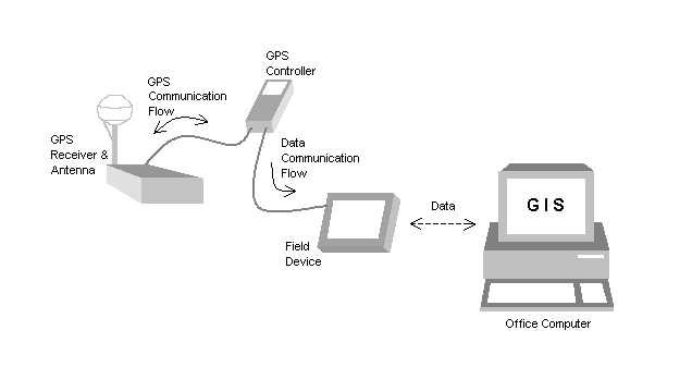
Position-focused integration is, historically, the most common approach to GPS integration (as opposed to interaction). As depicted in Figures 2a. and 2b., position-focused integration generally consists of a complete GPS system supplying a separate field application with GPS derived data that is related solely to the computation of positions. Data from the GPS is commonly transmitted to the field device using the NMEA-0183 protocol, although this is not the only protocol used. NMEA-0183 is a strictly defined ASCII-based format that consists of several messages, which contain data that's packaged and sent to an external device. Data from the field device may be transferred to and from the enterprise GIS. This is not imperative however, as the field application may be a self contained GIS in its own right.
Conceptual representation of position-focused integration using two field devices
Figure 2a. Conceptual representation of position-focused integration using two field devices
Figure 2a. presents a good perspective on the components associated with position-focused integration. Position-focused integration essentially uses a GPS system, which could be the same as that used in data-focused integration, to provide data directly into an application running on the field device. In effect, the GPS system is treated as an external sensor by the application on the field device. The field device will usually provide data storage.
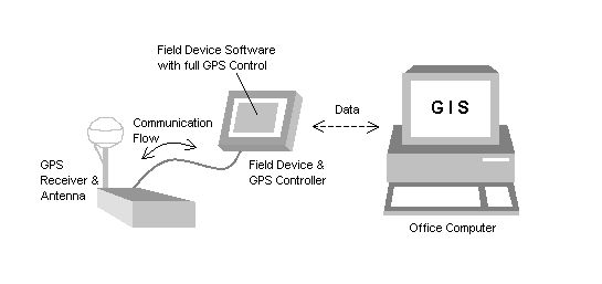
Conceptual representation of position-focused integration using a single field device
Figure 2b. Conceptual representation of position-focused integration using a single field device
With the advances in handheld field devices, it is becoming more common to find both the GPS control application and the field device application operating on the same device, as depicted in Figure 2b. It’s important to note though that the applications will be operated totally separate to one another. In general, one application is used to configure the GPS receiver and control the provision of position related data, while another application is used to store and use the data that is being sent to it. It's important to note that the data storage application has little or no control over the operation of the GPS equipment.
While systems that make use of position-focused integration can become cumbersome, from an equipment and ease of use perspective, and expensive they are very useful when GPS positioning is required on an infrequent basis. An organization, for example, may already have a complete GPS system for data collection purposes but may have another application that can make use of GPS from time to time. The ability to utilize the GPS system when GPS is useful makes good economic sense. The downside of losing a tight integration with the GPS receiver or carrying a cumbersome system may be an acceptable alternative to the expense required to fully customize a system.
An example of position-focused integration is seen through the use of Trimble Navigation's GPS Pathfinder Controller software to setup a GPS Pathfinder XRS receiver for use with Esri's ArcPad field-GIS product. While ArcPad is actually able to power on and connect to a GPS Pathfinder XRS receiver directly, it has not been designed to configure the GPS receiver directly. The Pathfinder Controller software acts as the controlling device for the GPS receiver, while ArcPad provides an interface that is designed well for image display and spatial query.

Technology-focused Integration

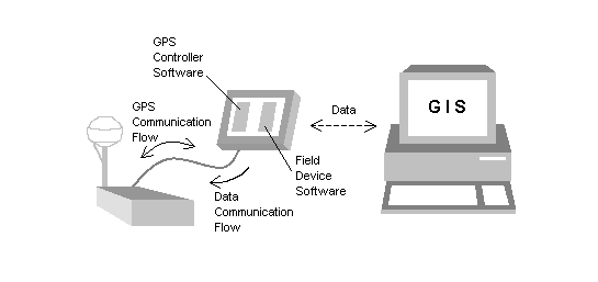
 Technology-focused integration is a refinement of position-focused integration. As Figure 3 illustrates, control of the GPS hardware is achieved directly from a third party application, thus eliminating the need for a separate application or device to control the GPS receiver. Communication between the application and the GPS receiver has a two-way communication flow - as compared to the one-way flow associated with the secondary application and the GPS system in the position-focused approach. As with position-focused integration, it is optional for data to be transferred between the field device and the enterprise GIS. The transfer of data is dependant on the capabilities of the application on the field device.
Conceptual representation of technology-focused integration
Figure 3. Conceptual representation of technology-focused integration
This ability for a customized application to communicate directly with the GPS receiver enables GPS and GIS technologies to truly be integrated together in a seamless manner. In fact, the GPS technology is able to be totally embedded within a GIS application system to an extent that an end-user of the system will think that technologies from two different organizations actually came from one single source. Thus making a technology-focused application very similar to a data-focused system. The advantage though is that the full power of the GIS can also be taken directly into the field. The user-interface and functionality of the application can be totally designed around the needs of the user - resulting in powerful spatial analysis systems that are familiar and easy to use for the person who is going to use it most.
The reason that GPS receivers can be so tightly integrated is not new, but the current state of software technology has made a technology-focused integration approach more readily accessible to more people. Technology-focused integration requires a developer to be able to create programs using the raw (often proprietary) language (or protocol) of the GPS receiver. Proprietary protocols are generally in a binary format and can be very complex and complicated - at least for those who are not expert programmers. This has often meant that the development of customized GPS-based applications has been a costly exercise.
Now, however, through the use of component technologies (such as ActiveX components), it's significantly easier to integrate GIS and GPS components within the same programming code - or application. Software development products are emerging from within the GPS industry that takes the complex, but powerful, proprietary protocol of the GPS receiver and makes it simple to use and understand by 'wrapping' an ActiveX application programming interface (API) around the proprietary protocol. ActiveX components follow clearly defined rules for interacting with applications. Such standardized interaction allows the same control to be used in several different contexts. The applications are typically developed within Microsoft's Visual Basic, Visual C++ or VBA development environments, but ActiveX controls also operate in additional development environments.
As with the GPS industry, components are also available from GIS vendors, such as Esri's MapObjects ActiveX product. Because GPS and GIS ActiveX components adhere to a standard and commonly used API structure, the power that was once restricted to the large companies that develop GIS and GPS products is now readily available to all, enabling unique and powerful, user-specific solutions to be easily created.
The most significant advantage of a technology-focused integration approach is the flexibility it offers for both end-users and application developers alike. Although ActiveX has made it easy to develop applications using proprietary protocols, the programmer time required to develop customized applications can still make it prohibitively expensive. For that reason, technology-focused integration is best suited to very simple applications or applications that are complex in nature and cannot be catered for by an off-the-shelf system. For the majority of GIS professionals who make use of GPS, therefore, a data-focused integration approach often provides the most economical solution.
ActiveX components also exist for position-focused integration techniques, so it’s important to look closely at the component to ensure it provides the level of functionality that you expect. When looking for an appropriate GPS-based ActiveX component it's important to consider:
  • The level of control offered over the GPS receiver's settings and status messages;
  • The level of flexibility associated with the computation of positions and their associated levels of accuracy; and
  • The provision of adequate information that provides confidence in the quality and use of the positions that are being supplied.
An example of technology-focused integration is the use of Trimble Navigation's Pathfinder Tools™ software development kit to integrate a GPS Pathfinder XRS receiver within a customized application that uses Esri's MapObjects product to visually display a map and carry out spatial analysis directly on a pen-based field computer.

Conclusion


There are numerous ways that GIS and GPS technology can (and already do) work well together. From complete off-the-shelf data collection and data maintenance systems, to help with the management of spatial features and attribute data, through to very flexible software development kits, to assist in the creation of unique and sophisticated field applications. The use of GPS within a GIS environment has already been well accepted and proven - especially for data collection and now data maintenance. The manner in which GPS is used with GIS is now wide and varied allowing users to determine the way GIS and GPS are used together to best meet their needs

Friday 12 December 2014

How to create a simple python add-in tool for ArcGIS Desktop

How to create a simple python add-in for ArcGIS Desktop


TOOL USED:  Python Add-in Assistant

WORKING OF THE TOOL:
Creating a Simple python add-in assistant for ArcGIS Desktop to add a Fishnet table to the ArcMap using the python
Type of Python Add-in: Tool Type
Function: At the end of drawing a rectangle on the ArcMap a fishnet with specified rows and columns should appear on the Screen
A python add-in tool is very similar to a button. But, a tool requires user to interact with the map application based on that interaction some business logic will get executed. The Zoom In tool Description: Zoom In in ArcMap will be a great example, when the user draws a rectangle on the ArcMap ,then the map will be redrawn with that rectangle as an extent.
Below steps will help you to create both Toolbox as well as a Tool on it

PROCEDURE:
Steps to Create a Toolbar for your Tool:
1.     To create your own toolbar. Open the Add-n assistant and Go to Add-in Contents tab and give the information about the add-in which you are going to create.
Note: A tool can reside on a Toolbar but cannot sits on a Menu
2.     Click the Add-In Contents tab and begin declaring your add-in customizations. A tool can reside on a toolbar but not on a menu. See creating an add-in toolbar for more detailed procedure.
3.     To Create the tool on your new Toolbar
Right-click the new toolbar and choose New Tool on the right click Menu.
Python addin assistant window

At once you have finished giving out the information and details about the add-in. Click on Save button at the bottom of the wizard. All the necessary files and folders will get created within the working folder of your add-in assistant.
Now it is the time to work on the main code. Go to the python script located on the install folder and open it using your Python idle. Code will appear as shown below with the class name same as your button name.
Note: Do not change the button name as it is directly linked with the button and registered in the your Config.xml file

 
Onclick() methof of the addin button class
The Onclick () method shown on idle will get executed on when the user click on the tool . But I our case the fishnet should get created whenever the user draw the tool is selected and draw an rectangle on the Map. So to do that OnRectangle () method of the python add-in will comes in to Picture. Replace on click method with OnRectangle () method as shown below:


Fishnet content added to On Rectangle method


·         The code will check for any preexistence of fishnet on the memory using the Exist() Method and deletes if anyone is already there using the Delete_Management() function.
·         CreateFishnet_management is the core function which is going to do the actual work after supply all the necessary parameters to it
·         Refresh the active view to redraw the Map and return the path of the fishnet to the calling function.


How to check for condition in Geoprocessing Service or Model Builder

How to check for if/else conditions in Geoprocessing Service


TOOL USED:  
Arc python and Script tool
Python script will be deployed in the ARC Toolbox to create the Conversion Tool 

WORKING OF THE TOOL:
Script tool is created in the ArcMap and the required input & Output Parameter are set. The script tool source is set to the custom python code present in an Python file(.py)
Out motive is to use check for the count of a features in an feature class and performing an conditional Execution

PROCEDURE:
  • Open ArcMap 10.0+ 
  • Create your own Geometric Network or Open your Existing Geometric Network
  • Add your Geometric network to the Table of contents in the ArcMap as Shown Below


·         Create a new Model in your myToolBox .Right Click on MyToolBox > New > Model.Following window will appear on the Screen 


  •    Add your desired feature class to the Model. (Right Click on any empty space and select ADD DATA  and select your feature class in the object browser)
  • ·         Add Get Count and Calculate value Model from the System Toolbox Connect the model as shown below 


  • ·         Now open calculate value Model and in the Expression Textbox call the function Calculate(%RowCount%)
  • ·         Here %RowCount% will act as an Inline Variable and Compiler automatically replace the %RowCount% with the value of the rowcount field
  • ·         At the Code block defined the function Calculate as

def calculate(row):
if row>0:
return true
else:
return false
  • ·         Make the return Data type as Boolean
  • ·         The output Boolean can be set as a precondition for any model. So that the Model  get executes only when the output of calculate value is true


How to create Graphical User Interface in Arcpy

To Show GUI in your Script tool of your ArcMap


Python consist of  huge number of GUI frameworks (or toolkits) available for it, from TkInter to a number of other cross-platform solutions.

In your case we going to use the default TkInter Module to access the windows form from the python script tool.
TkInter is being proposed as the most interactive and easy to program module in Python GUI framework

1. Create a new Script tool in the Arcmap's ArcCatalog window in your desired location
2. Copy the below codes in to a notepad file and save it as python .py extension
3.Go to the script tool and Right Click > Properties > Parameter
4.Browse to your newly created python code as the source file to execute
5.All is well.Start GUI python from TkInter. Happy Programming


from Tkinter import *
import datetime
from array import *


root = Tk()
logo = PhotoImage(file="Image.Gif")
w2 = Label(root,
           image=logo).grid(row=0,column=1)
explanation = """Team Geo Zoner"""
w2 = Label(root, 
          compound = CENTER,
           fg="Red",
           bg="black",
           font="Times 55 bold",
          text=explanation)
w2.grid(row=0,column=0)

p=str(datetime.datetime.now().isoformat())
texter="Your Heading Goes Here"+str(p);
w3 = Label(root, 
          compound = CENTER,
           fg="Green",
           font="Times 20 bold",
          text=texter)
w3.grid(row=1,column=0)

Parameters = ['Number of Inputs','Number of Ouputs','Number of Processing Parameters','Number of Intermediate data']

r = 2
i=1
for c in Parameters:
    Label(text=c, relief=RIDGE,width=25).grid(row=r,column=0)
    Entry(text="Value", relief=SUNKEN,width=10).grid(row=r,column=1)
    r = r + 1
    i = i + 1

root.title("GISSTUDY")
root.mainloop()

Thursday 11 December 2014

Performance issues on ArcGIS Geoprocessing Service

How to improve Geo-processing Execution Speed

Geoprocessing services hosted in the ArcGIS server needs to be pretty fast and accurate. User will always want the service to be the fastest. Since ArcGIS Server will be able to service multiple users at one instant of time, inefficient services can overload your server and increase the processing time. The more efficient and intelligent your services, the more users can be serviced with the same computing resources at a smaller amount of time.

Below are some of the tips and techniques that helps in increasing the performance of your Geo-processing Services.

Use local paths to data and resources

The more faster the data requires to be processed is accessible by the server the more faster your service will be.It is good to copy your data to the server rather than placing it on the shared location and asking the server to access it.(Copying the server will be effective only if the Geo processing input data is very small in size and also when the input data is not dynamic)
Reading data from the local area network will be slow compared to accessing the data from the local disk.. 


Reading and Writing the Intermediate data IN_Memory


The service execution speed will get increased by multiple times when the intermediate data is allowed to stored in the machine memory(RAM).Input and output operation is the slowest of all the computing operations.In Geoprocessing storing the intermediate data in a file geodatabase or personnel Geodatabase will take maximum of the execution time.
Please be sure the data which your are storing in the memory as an intermediate data need not be necessary after the execution is complete.Because once the execution is complete the data in the memory will get cleared.Don't write large amount of data to the in_memory as it may affect the performance of the processing service.
To write to your computer's memory, use the pathname in_memory, as follows:
          in_memory\your featureclassname


Use layers from a source map document

If a service uses a source map document instead of feature classes and datasets, it will tremendously increase the performance of the service.Your models and scripts can use map layers from the source map document so that it will impose less load on the processor and significantly decrease the execution time. A layer references a dataset on disk or feature class on a geodatabase, and some layers cache properties about the dataset. Therefore by using dataset layer instead of the direct dsataset or feature class,there is a performance advantage because ArcMap opens the dataset once, caches basic properties of the dataset, and keeps the dataset open. When the Service executes, the dataset need not to be  reopened because the source map document already it is opened and it will gives us a performance boost.


Write data to shapefiles

Storing the data to shapefiles is a bit faster than writing to other formats but writing data to memory, described above, is the fastest of all. Even then there is further more limitations on the shapefiles such field names should be  as 10 character , no null values, and limited support for date/time, to name a few. This become more helpful if the you are running your model locally on your Desktop

Tuesday 9 December 2014

ArcObjects to add a flag to the Geometric Network .Net

Creating a Flag in ArcMap using ArcObjects .NET


1. Add a new add-in component to the CreatingOutputs solution and name the component
AddFlagTool. Select Tool as the type of add-in, set the confi guration of the tool as shown in

2. Enter the following using directives at the top of the AddFlagTool.cs fi le’s code window:
using ESRI.ArcGIS.ArcMapUI;
using ESRI.ArcGIS.Geometry;
using ESRI.ArcGIS.Display;
using ESRI.ArcGIS.Carto;
3. You are going to write the code for handling the OnMouseDown event. In other words, you want
your code to be executed when a user clicks somewhere in the main window of the software application. Because all the events and their handlers are defined in the base class of all tools(ESRI.ArcGIS.Desktop.AddIns.Tool), you have to override the necessary handlers. So write
the following code in the AddflagTool.cs file inside the definition for the AddflagTool class and outside of any method: protected override
As soon as you type these two keywords and press the spacebar, you will see the list of all available handlers.
Find OnMouseDown in the list as shown in  below Figure and press Enter.


4.On the Mouse down event call the add flag function in the another library

5.For the Add flag function add the following code in the other library addflag function

        public static void AddFlag(IPoint pPnt, IApplication app, double snapTol)
        {
            //IProgressDialogFactory pProDFact = null;
            //IStepProgressor pStepPro = null;
            //IProgressDialog2 pProDlg = null;
            //ITrackCancel pTrkCan = null;
            IGeometricNetwork gn = null;
            IPoint snappedPoint = null;
            IFlagDisplay pFlagDisplay = null;
            INetFlag startNetFlag = null;

            INetworkAnalysisExt pNetAnalysisExt = null;
            IMap pMap = null;
            UID pID = null;
            int EID = -1;


            try
            {

                pID = new UID();

                pID.Value = "esriEditorExt.UtilityNetworkAnalysisExt";
                pNetAnalysisExt = (INetworkAnalysisExt)app.FindExtensionByCLSID(pID);
                gn = pNetAnalysisExt.CurrentNetwork;

                pMap = (app.Document as IMxDocument).FocusMap;
                startNetFlag = Globals.GetJunctionFlagWithGN(ref pPnt, ref pMap, ref gn, snapTol,out snappedPoint, out EID, out  pFlagDisplay, true) as INetFlag;
                if (startNetFlag == null)
                {
                    //startNetFlag = Globals.GetEdgeFlag(ref pPnt, ref pMap, ref gnList, snapTol, ref gnIdx, out snappedPoint, out EID, out distanceAlong, out  pFlagDisplay, true) as INetFlag;
                }


                if (app != null)
                {
                    
                    Globals.AddFlagToGN(ref pNetAnalysisExt, ref  gn, ref pFlagDisplay);
                    //  pFlagDisplay
                    pNetAnalysisExt = null;
                    pID = null;

                }


            }
            catch (Exception)
            {
                
                throw;
            }
        }
5. The above function will make a call to the getJunctionflag code.create a function block called "getjunctionflag" with the class library Global  and place the below code:


using System;
using System.Collections.Generic;
using System.Linq;
using System.Text;
using ESRI.ArcGIS.SystemUI;
using ESRI.ArcGIS.Geometry;
using ESRI.ArcGIS.GeoDatabaseUI;
using ESRI.ArcGIS.Geodatabase;
using ESRI.ArcGIS.Framework;
using ESRI.ArcGIS.esriSystem;
using ESRI.ArcGIS.Display;
using ESRI.ArcGIS.DataSourcesGDB;
using ESRI.ArcGIS.DataSourcesFile;
using ESRI.ArcGIS.CartoUI;
using ESRI.ArcGIS.Carto;
using ESRI.ArcGIS.ArcMapUI;
using ESRI.ArcGIS.ArcMap;
using ESRI.ArcGIS.NetworkAnalysis;
using ESRI.ArcGIS.NetworkAnalyst;
using ESRI.ArcGIS.EditorExt;


namespace Toolkit
{
    class Globals
    {
        public enum GNTypes
        {
            Flags = 1, Barries = 2, Results = 3

        };

        public enum flagType { EdgeFlag, JunctionFlag, EdgeBarrier, JunctionBarrier };
    

        public static IJunctionFlag GetJunctionFlagWithGN(ref IPoint point, ref IMap map, ref IGeometricNetwork gn, double snapTol, out IPoint snappedPoint, out int EID, out  IFlagDisplay pFlagDisplay, bool Flag)
        {
            //Initialize output variables
            snappedPoint = null;
            EID = -1;
            pFlagDisplay = null;
            int FCID = -1, FID = -1, subID = -1;

            IGeoDataset pDS = null;
            IPointToEID pointToEID = null;
            INetElements netElements = null;
            INetFlag junctionFlag = null;
            try
            {
                pFlagDisplay = null;

                pDS = gn.FeatureDataset as IGeoDataset;
                point.Project(pDS.SpatialReference);


                pointToEID = new PointToEIDClass() as IPointToEID;

                // find the nearest junction element to this Point
                pointToEID.GeometricNetwork = gn as IGeometricNetwork;
                pointToEID.SourceMap = map;
                pointToEID.SnapTolerance = snapTol;

                try
                {
                    pointToEID.GetNearestJunction(point, out EID, out snappedPoint);
                }
                catch (Exception ex)
                {

                }


                if (snappedPoint == null)
                    return null;

                // convert the EID to a feature class ID, feature ID, and sub ID
                netElements = gn.Network as INetElements;

                try
                {
                    netElements.QueryIDs(EID, esriElementType.esriETJunction, out FCID, out FID, out subID);
                }
                catch (Exception ex)
                {

                    return null;
                }

                //Create flag for start of trace
                junctionFlag = new JunctionFlagClass() as INetFlag;
                junctionFlag.UserClassID = FCID;
                junctionFlag.UserID = FID;
                junctionFlag.UserSubID = subID;

                if (junctionFlag is IEdgeFlag)
                {
                    pFlagDisplay = new EdgeFlagDisplayClass();

                    if (Flag)
                        pFlagDisplay.Symbol = CreateNetworkFlagBarrierSymbol(flagType.EdgeFlag) as ISymbol;
                    else
                        pFlagDisplay.Symbol = CreateNetworkFlagBarrierSymbol(flagType.EdgeBarrier) as ISymbol;
                }
                else
                {
                    pFlagDisplay = new JunctionFlagDisplayClass();
                    if (Flag)
                        pFlagDisplay.Symbol = CreateNetworkFlagBarrierSymbol(flagType.JunctionFlag) as ISymbol;
                    else
                        pFlagDisplay.Symbol = CreateNetworkFlagBarrierSymbol(flagType.JunctionBarrier) as ISymbol;
                }

                pFlagDisplay.ClientClassID = FCID;
                pFlagDisplay.FeatureClassID = FID;
                pFlagDisplay.SubID = subID;
                pFlagDisplay.Geometry = snappedPoint;

                return junctionFlag as IJunctionFlag;
            }
            catch
            {
                return null;
            }
            finally
            {
                pDS = null;
                pointToEID = null;
                netElements = null;

            }


        }

        public static ISimpleMarkerSymbol CreateNetworkFlagBarrierSymbol(flagType flgType)
        {
            ISimpleMarkerSymbol pSymbolFlag = null;
            switch (flgType)
            {
                case flagType.EdgeFlag:
                    pSymbolFlag = new SimpleMarkerSymbolClass();
                    pSymbolFlag.Style = esriSimpleMarkerStyle.esriSMSSquare;
                    pSymbolFlag.Angle = 0;
                    //pSymbolFlag.Color = 
                    pSymbolFlag.Outline = true;
                    pSymbolFlag.OutlineSize = 1;
                    //pSymbolFlag.OutlineColor = GetColor(0, 0, 0);
                    pSymbolFlag.Size = 10; //TODO: UserConfig
                    break;
                case flagType.JunctionFlag:

                    pSymbolFlag = new SimpleMarkerSymbolClass();
                    pSymbolFlag.Style = esriSimpleMarkerStyle.esriSMSCircle;
                    pSymbolFlag.Angle = 0;
                    //pSymbolFlag.Color = GetColor(0, 255, 0);
                    pSymbolFlag.Outline = true;
                    pSymbolFlag.OutlineSize = 1;
                    //pSymbolFlag.OutlineColor = GetColor(0, 0, 0);
                    pSymbolFlag.Size = 10; //TODO: UserConfig
                    break;
                case flagType.EdgeBarrier:


                    pSymbolFlag = new SimpleMarkerSymbolClass();
                    pSymbolFlag.Style = esriSimpleMarkerStyle.esriSMSDiamond;
                    pSymbolFlag.Angle = 0;
                    //pSymbolFlag.Color = GetColor(255, 0, 0);
                    pSymbolFlag.Outline = true;
                    pSymbolFlag.OutlineSize = 1;
                    //pSymbolFlag.OutlineColor = GetColor(0, 0, 0);
                    pSymbolFlag.Size = 10; //TODO: UserConfig
                    break;
                case flagType.JunctionBarrier:

                    pSymbolFlag = new SimpleMarkerSymbolClass();
                    pSymbolFlag.Style = esriSimpleMarkerStyle.esriSMSX;
                    pSymbolFlag.Angle = 0;
                    //pSymbolFlag.Color = GetColor(255, 0, 0);
                    pSymbolFlag.Outline = true;
                    pSymbolFlag.OutlineSize = 1;
                    //pSymbolFlag.OutlineColor = GetColor(0, 0, 0);
                    pSymbolFlag.Size = 10; //TODO: UserConfig
                    break;
                default:
                    pSymbolFlag = new SimpleMarkerSymbolClass();
                    pSymbolFlag.Style = esriSimpleMarkerStyle.esriSMSCircle;
                    pSymbolFlag.Angle = 0;
                    //pSymbolFlag.Color = GetColor(0, 255, 0);
                    pSymbolFlag.Outline = true;
                    pSymbolFlag.OutlineSize = 1;
                    //pSymbolFlag.OutlineColor = GetColor(0, 0, 0);
                    pSymbolFlag.Size = 10; //TODO: UserConfig
                    break;
            }
            return pSymbolFlag;

        }

        public static void AddFlagToGN(ref INetworkAnalysisExt pNetworkAnalysisExt, ref ESRI.ArcGIS.Geodatabase.IGeometricNetwork pGeomNet, ref  IFlagDisplay pFlagDsiplay)
        {
            INetworkAnalysisExtFlags pNetworkAnalysisExtFlags = null;

            try
            {
                if (pNetworkAnalysisExt.CurrentNetwork != pGeomNet)
                {
                    pNetworkAnalysisExt.CurrentNetwork = pGeomNet;
                }


                pNetworkAnalysisExtFlags = (INetworkAnalysisExtFlags)pNetworkAnalysisExt;


                if (pFlagDsiplay is IEdgeFlagDisplay)
                {

                    pNetworkAnalysisExtFlags.AddEdgeFlag(pFlagDsiplay as IEdgeFlagDisplay);

                }
                else
                {

                    pNetworkAnalysisExtFlags.AddJunctionFlag(pFlagDsiplay as IJunctionFlagDisplay);
                }
            }
            catch
            {

            }
            finally
            {
                pNetworkAnalysisExtFlags = null;
            }


        }
    }
}

6. Run code and set the default debug application as ArcMap

7. Once the ArcMap is open go to customise code and in the command tab add the tool to your window

8.click on the tool will add an flag symbol to the map(use f5 to refresh the map)